Innovating the Path to Terabit Speeds: IEEE, Senko, and US Conec Weigh In
To support emerging technologies and ever-increasing amounts of data, large hyperscale and cloud data centers like AWS, Google Cloud, Meta, Microsoft Azure, and Equinix have quickly migrated to 400 Gigabit speeds for switch-to-switch links and data center interconnects, as well as for switch-to-server breakout configurations. Now these big-name data centers are gearing up to deploy 800 Gig and looking ahead to 1.6 and 3.2 Terabit speeds, while 400 Gig starts making its way into large and even mid-sized hosted and enterprise data centers. That’s no surprise, given that the volume of data generated worldwide is predicted to exceed 180 zettabytes, with hyperscale and cloud data centers accounting for 95% of total traffic.
A New Level of Signaling
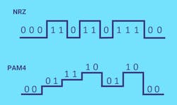
A significant innovation for achieving viable 800 Gig and 1.6 Terabit speeds is the 100 Gig signaling rate per lane using four-level pulse amplitude modulation signaling technology, PAM4. With four voltage levels compared to the two of non-return to zero (NRZ) signaling, PAM4 doubles the number of bits that can be transmitted in the same signal period, as shown in Figure 1. NRZ uses high and low levels representing 1 and 0 to transmit one bit of logic information, while PAM4 uses four levels representing 00, 01, 11, and 10 to transmit two bits of logic information. With the bit levels closer, PAM4 modulation is more sensitive to signal-to-noise ratio (SRN) than NRZ.
PAM4 100 Gig signaling rate per lane was chosen by IEEE 802.3 for 4-lane 400 Gig applications. Based on this PAM4 signaling, 800 Gig requires 8 lanes and 1.6 Terabit requires 16 lanes. Efforts are also underway by various industry forums to develop a 200 Gig per lane rate modulation.
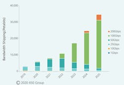
“To achieve faster transmission speeds, the trend has been to add more lanes, which is the initial approach for 800 Gig and 1.6 Terabit. But if the industry can achieve a 200 Gig signaling rate per lane, it will transform Terabit applications,” says Tiger Ninomiya, Senior Technologist for Senko. “As a familiar technology, PAM4 is the primary consideration for achieving 200 Gig signaling.” Achieving 200 Gig PAM4 is technologically challenging and not expected to be available in the market until at least 2024. The 100 Gig signaling rate per lane will remain the predominant approach for several more years, as shown in Figure 2.Ongoing Transceiver Transformation
Alongside advancements in signaling technology, pluggable transceiver technology has evolved through the efforts of various multi-source agreement (MSA) groups formed by leading equipment vendors like Cisco, Nokia, Intel, Broadcom, Juniper, and Arista, as well as hyperscalers and a variety of cable and connectivity manufacturers.
The 8-lane QSFP-DD and OSFP pluggable transceiver form factors developed to support 400 Gig using a 50 Gig signaling rate per lane have now advanced to support 800 Gig with 100 Gig signaling (referred to as QSFP-DD800). Four-lane QSFP112 transceivers based on a 100 Gig signaling rate per lane were also introduced to provide advantages on density and cost in 400 Gig applications.
When a 200 Gig signaling rate per lane becomes available, these transceiver form factors can adapt to 4-lane 800 Gig, 8-lane 1.6 Terabit, and 16-lane 3.2 Terabit. In the interim, 16-lane variations can support 1.6 Terabit based on a 100 Gig signaling rate per lane. Double-stacked QSFP-DD800 and dual-row OSFP-XD form factors already double the number of lanes from 8 to 16 to support 1.6 Terabit. Future 3.2 Terabit transceivers based on a 200 Gig signaling rate per lane could use the same double-stacked and dual-row form factors.
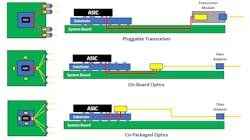
For data center interconnects and hypercomputing applications, ultra-high bandwidth based on 1.6 and 3.2 Terabit comes with power consumption concerns. One option is to move the electro-optic conversion process closer to the application-specific integrated circuit (ASIC). Possibilities include onboard optics (OBO) and co-packaged optics (CPO) that mount the transceiver on the system board or on the same substrate as the ASIC, rather than the current chip-to-module approach with pluggable transceivers as shown in Figure 3.
While OBO and CPO are ideal for lowering power consumption, there is much debate regarding their viability compared to pluggable transceivers. Serviceability is the primary concern with OBO and CPO due to the electro-optic interface moving inside the switch. “We’ve been supporting onboard optics in high-performance computing for decades and have witnessed various alternatives to front panel pluggable optics, but they come with tradeoffs,” says Tom Mitcheltree, Advanced Technology Manager for US Conec. “Pluggable transceivers remain the preferred technology due to serviceability—if one fails, it’s easily replaced without disturbing the other ports. With onboard and co-packaged optics, a failure means you’re pulling out the switch and taking down all the ports. One could argue there is a direct line of sight for pluggable transceivers to support a 51 Tb switch with 32 ports of 1.6 Terabit, and eventually a 102 Tb switch with 3.2 Terabit ports.”
Most industry experts agree that data centers will not transition to OBO or CPO until there is no other option to reduce power consumption, and advancements in cooling technologies could further delay adoption. Senko’s Tiger Ninomiya agrees that pluggable transceivers will remain for lower-level leaf and spine data center switches. He says, “OBO and CPO will likely be initially adopted as a discrete non-standardized technology in the hypercomputing hyperscale environment for emerging technologies such as AI, machine learning, and XPU disaggregation.”
Strategic Standards at Work
While the optics continue to advance for 800 Gig and beyond, standards bodies are already working to develop the objectives for media access control and physical layer parameters. In December 2022, IEEE split the 800 Gig and 1.6 Terabit standards efforts in the IEEE P802.3df project into two separate projects—one based on 100 Gig signaling (802.3df) expected for completion in mid-2024 and the other on future 200 Gig signaling or greater (802.3dj) expected for completion in Q2 2026.
The current 802.3df draft objectives enable 800 Gig over 8 pairs of multimode and single mode fibers, with 8 fibers transmitting and 8 receiving at 100 Gig. The standard will include multimode 800GBASE-VR8 to 50 meters (m), multimode 800GBASE-SR8 to 100 m, single mode 800GBASE-DR8 to 500 m, and single mode 800GBASE-FR8 to 2 kilometers (km).
“Standards tend to build upon prior generations, and the development of 800 Gig and 1.6 Terabit Ethernet follows that path. To that end, the IEEE P802.3df project made rapid progress on objectives based on leveraging existing 100 Gig per lane standards, as no new development of the underlying signaling technologies is necessary,” says John D’Ambrosia, chair of IEEE P802.3df Task Force and acting chair of the IEEE P802.3dj Task Force.
The 802.3dj draft objectives for 800 Gig and 1.6 Terabit based on future 200 Gig include two 800 Gig variants—one over 4 pairs of single mode fiber and one over 4 wavelengths over a single pair of single mode fiber—and 1.6 Terabit over 8 pairs of single mode fiber as shown in Table 1. “The development of 200 Gig per lane signaling for the various physical mediums being targeted will be a key aspect of the heavy lifting that the P802.3dj Task Force will undertake,” says John D’Ambrosia. “The importance of minimizing power and latency for 800 Gig and 1.6 Terabit Ethernet cannot be understated.”
As of April 2023, 1.6 Terabit over multimode fiber was not proposed or included in 802.3dj draft objectives, as indicated in Table 1. However, John D’Ambrosia says, “Based on historical perspective, one could anticipate that the 1.6 Terabit Ethernet family will eventually include solutions to address multimode fiber.” It also remains to be seen how 3.2 Terabit applications will shape up. The first iterations could operate over 16 pairs of single mode fiber via MPO-32 or two MPO-16 connectors, depending on market need and acceptance of a 16-lane solution.
“Serial lane and 4-lane based Ethernet solutions have traditionally found significant market adoption. The decision to include objectives for an 8-lane approach was based on data that indicated market adoption. While approaches that could support 16 lanes were discussed, no data indicating market adoption has been shared at this time,” says John D’Ambrosia. “However, given Ethernet’s history and observed bandwidth trends over the past twenty years, the need for 3.2 Terabit Ethernet in the future would not be a surprise.” Given the perceived challenges in developing higher-speed signaling and the need for low-latency solutions that might limit more complicated modulation approaches, going from an 8-lane to a 16-lane approach seems a future consideration.
“The development of IEEE 802.3 projects is consensus driven with the P802.3dj Task Force Task Force containing subject matter experts from a variety of backgrounds—users and producers of systems and components for high-bandwidth applications, such as cloud-scale data centers, internet exchanges, colocation services, content delivery networks, wireless infrastructure, service provider and operator networks, and video distribution infrastructure,” says John D’Ambrosia. “This pool of talent enables Ethernet to continue its evolution to satisfy the needs of industry. ”
Addressing Reflectance Concerns
While standards bodies have not yet developed performance parameters for 800 Gig and 1.6 Terabit applications, higher sensitivity to noise with PAM4 signaling and ever-increasing insertion loss requirements continue to present a challenge. Short-reach DR and FR single mode applications that leverage cost-effective, lower-power lasers with relaxed specifications have more stringent maximum channel insertion loss requirements compared to long-haul LR and ER single mode—3 dB and 4dB for DR and FR applications compared to greater than 6 dB and 15 dB for LR and ER applications. These applications are also more susceptible to reflectance, so industry standards have specified discrete reflectance values based on the number of mated pairs in the channel. Not achieving these values can reduce the maximum channel insertion loss in DR and FR applications.
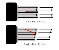
Some data centers have adopted APC MPO-16 multimode connectors for 400 Gig deployments. Many will do the same with 800 Gig, but it is not required. “There’s been significant discussion around APC multimode connectivity within the standards bodies. While APC delivers better reflectance, it’s not necessarily required to meet next-generation multimode specifications—especially if you’re deploying connectors from quality assembly houses and manufacturers that ensure proper endface geometry,” says US Conec’s Tom Mitcheltree. “Plus, it may be challenging for the industry to migrate entirely to APC when there is so much flat multimode deployed worldwide in data centers. That’s why the standards allow both.”
Downsizing the Duplex
A typical deployment for 800 Gig and 1.6 Terabit will be breakout applications where a single switch port supports multiple 100 Gig duplex connections or future 200 Gig duplex connections. The bulk of initial 800 Gig deployments will be 8 X 100 Gig, which allows data centers to maintain high-speed uplinks while supporting multiple lower-speed switch or server connections to maximize switch port utilization and reduce equipment size.
Hybrid MPO-to-duplex fan-out cables or MPO-to-duplex cassettes can create breakout links. Fan-out cables create congestion and can be challenging to reconfigure in complex environments. Plus, if there’s a problem with the cable, 8 duplex connections need to come offline. MPO-to-duplex cassettes offer greater flexibility within patching fields that use individual jumpers to make the 100 Gig connections. Whether using fan-out cables or cassettes, density is an issue in breakout applications. Leading connectivity vendors Senko and US Conec are addressing this issue by developing very small form-factor (VSFF) duplex connectors.
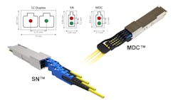
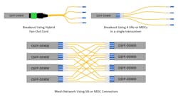
Senko’s SN and US Conec’s MDC VSFF duplex connectors are more than 70% smaller than traditional LC duplex connectors, as shown in Figure 5. Consider a breakout application that leverages a 16-fiber 800 Gig port to create 8 100 Gig duplex connections. A 64-port 51.2 Terabit switch in this scenario supports 512 duplex 100 Gig connections. Using traditional LCs in a 1U high-density 96-port fiber patch panel would require six panels. The number of panels is cut in half with SN and MDC duplex connectors.Four SN or MDC connectors fit within a single QSFP footprint for deploying point-to-point breakout applications or a mesh topology in data center interconnect applications, as shown in Figure 6. This configuration is ideal for 800 Gig and 1.6 Terabit LR breakout applications using WDM, such as 4 X 200 Gig or 4 X 400 Gig.
New 16-Fiber Connectivity
Senko and US Conec also recently developed new multi-fiber VSFF connectors for 800 Gig and future 1.6 Terabit applications. As shown in Figure 7, the Senko SN-MT and US Conec MMC offer three times the density of a traditional MPO-16.
Considered the industry’s highest density connectors, SN-MT and MMC connectors are vertically positioned with four connectors fitting in a QSFP footprint. They come in low-loss APC multimode and single mode and feature push-pull boot technology. One and two-row variants are available with up to 32 fibers per connector.
“We took ergonomics very seriously when developing these smaller connectors. We focused on ensuring the MMC provides maximum density while remaining large enough to be tactile. The push-pull boot allows easy plug-in and removal of connectors without impacting adjacent ports,” says US Conec’s Tom Mitcheltree. “We’re especially excited about the MMC for structured cabling and the ability to fit more fibers into a patch panel. This makes a huge difference for data centers needing to distribute thousands of links.”
SN-MT and MMC connectors also accommodate double-stacked QSFP-DD800 and dual-row OSFP-XD form factors to support 16-lane (32-fiber) 1.6 Terabit applications using current 100 Gig signaling and future 16-lane 3.2 Terabit with 200 Gig signaling. Other applications these connectors facilitate include the deployment of preterminated trunks through pathways, with more connectors accommodated within a single pulling grip. They are also well suited for OBO and CPO as board-mounted connectors within the switch and as adapters at the front of a switch.
“Similar to MPO, multi-fiber VSFF connectors are versatile across multiple applications. In addition to structured cabling, we’re collaborating closely with hyperscalers and switch manufacturers for use with pluggable transceivers to support 16 and 32-fiber applications, including breakouts,” says Tom Mitcheltree. “They are also critical for onboard and co-packaged optics where more fiber density is needed.” With duplex and multi-fiber VSFF connectivity, data centers now have many options for supporting 800 Gig and 1.6 Terabit applications, as shown in Table 2.
Thinking Outside (or Inside) the Box
While industry experts, standards bodies, and leading manufacturers are all working to achieve commercially viable 800 Gig and 1.6 Terabit, savvy solutions providers keep abreast of the advancements and leverage new technologies. To that end, several vendors have entered into license agreements with Senko and US Conec to offer active equipment and fiber connectivity solutions with VSFF SN, SN-MT, MDC, and MMC connector interfaces.
One solution well suited for 800 Gig and 1.6 Terabit deployments is square patch panel cassettes versus traditional wide cassettes. The inherent nature of the square design supports more connectors to maximize the number of vertically positioned VSFF connectors. This square design can support 16 SN or MDC duplex connectors per cassette for a total of 192 duplex ports (384 fibers) in a 1U patch panel, as shown in Figure 8. Using new 16-fiber VSFF SN-MT and MMC connectors, square cassettes can support 3,072 fibers in a 1U panel for switch-to-switch and data center interconnect applications.The square format maximizes use space in a cassette format while providing the flexibility to support a range of form factors, including 8 duplex LCs, 16 duplex SNs or MDCs, or 16 SN-MTs or MMCs. This facilitates migration from 8 to 16 fiber applications or even 32 fiber applications if required. For example, an 800 Gig switch-ready square cassette with 16-fiber MPOs at the rear can easily adapt to future 1.6 Terabit or even 3.2 Terabit applications.
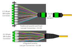
Another innovation well suited for 800 Gig and 1.6 Terabit breakout applications is cassettes that feature integrated cables rather than MPO connections at the rear. With traditional cassettes, the insertion loss of the rear MPO connection and the insertion loss of the front duplex connection must be factored into the insertion loss budget. The rear MPO connection on a traditional cassette is also an additional mated pair that can introduce reflectance. This is a potential risk in DR and FR short-reach single mode applications where the greater the number of mated pairs with discrete reflections above -55 dB, the lower the channel insertion loss.
With integrated cables, there is no rear MPO connection and associated insertion loss and reflectance to worry about. Instead, the incoming cable is directly terminated inside the cassette to the duplex ports at the front of the cassette, as shown in the example in Figure 9 (actual loss values will differ by manufacturer). Within the cassette, an integrated strain relief places the force on the strength members within the cable rather than the fibers themselves.
The square cassettes are also more easily pulled through pathways and snapped into a chassis. Having no MPO connection at the rear further speeds deployment by eliminating the need to remove pulling grips and install and plug together separate components.
A Viable Path Forward
As 800 Gig and future 1.6 and 3.2 Terabit applications come to fruition, there is no doubt that the industry will witness a multitude of solutions and innovations hitting the market over the next few years. The good news is that savvy industry leaders already have a good handle on the optical technology, standards development, and connector interfaces that will allow bold hyperscale and cloud data center trendsetters to deploy these speeds sooner rather than later. Large colocation and enterprise data centers won’t be far behind.
David Mullsteff is Chief Executive Office and Owner of Tactical Deployment Systems, which he founded to deliver fiber optic solutions focusing on quick-turn manufacturing and new product line development, including working with industry-leading manufacturers like Senko and US Conec to integrate their connectors. He is also the Chief Executive Officer and Owner of Cables Plus. To learn more, contact Tactical Deployment Systems.
Betsy Conroy is a Freelance Writer & Consultant with decades of ICT industry knowledge, combined with a keen ability to translate technical information into engaging copy. She delivers relevant, authoritative information on a variety of topics, including standards, data centers, IoT and IIoT, smart buildings, copper and fiber network technologies, wireless systems, industrial Ethernet, electrical transmission and distribution, electronic safety and security, digital lighting and more.

