Don’t Let Busway Be the Weak Link in Your DC Electrical Safety Chain
Andy Banks, Director of Databar Sales (North America) for Anord Mardix, explores in detail how the busway can efficiently and effectively distribute power throughout a data center environment.
Andy Banks, Director of Databar Sales (North America) for Anord Mardix
Electrical safety is of paramount importance in the data center industry. Awareness of electrical incident risks and preventive procedures (such as lock-out/tag-out) have become well established in the last decade. Nevertheless, in 2018 there were 160 deaths from electrical accidents and more than 1,500 injuries in the U.S. alone. Most operators and technicians are highly aware of safety protocols when working around live panels, but one electrical component that also demands caution is the busway
As the conduit for high-density, flexible power distribution for many data center applications, the busway needs to be a key element of any data center’s workplace safety considerations. Electrical conductors and bus bars are covered in the Occupational Safety and Health Administration (OSHA) standards 29 – CFR, including in Parts 1910.303, 1910.308, 1926.403 and 1926.408.
Busway has been defined by the National Electrical Manufacturers Association (NEMA) as “a prefabricated electrical distribution system consisting of bus bars in a protective enclosure, including straight lengths, fittings, devices, and accessories. Busway includes bus bars, an insulating and/or support material, and a housing.”
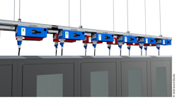
Figure 1. A typical overhead busway. (Photo: Anord Mardix)
Traditional Busway Practices & Challenges
Since its introduction within the automotive industry in the 1930’s, busway power distribution has become widespread in data centers and industrial facilities. Busway distribution systems in general have some common features. One of those is the need to couple together multiple sections of bus bar of up to 10-12 feet long to form the required length of busway. Traditionally, this coupling has been achieved by the addition of a separate set of components, commonly referred to as the “joint pack”. The joint pack typically comprises:
- 2 bus connectors
- 2 housing couplers
- 24 screws
In addition, a specialist tool is often required to install these components onto the busway. Installation time of eachjoint pack is typically up to five minutes dependent on the busway manufacturer. In a 40’ x 40’ busway run data hall, that can equate to two days of installation time. Mislay or mis-order any of those joint pack components and much larger installation delays may result.
Furthermore, given the critical nature of this busway coupler, annual thermography should be performed on each joint pack area to check for loose connections. Overall, this traditional installation method is very labor intensive, time-consuming, and poses an ongoing risk if there are any loose busbar connections.
Figure 2. A typical coupler for a traditional enclosed busway. (Anord Mardix)
Open Channel Busway Systems – A Partial Improvement
In recent years, the use of “open channel” busway has become commonplace. The open channel construction allows the plug-in (or tap off) sub-distribution units to be placed—theoretically—at any location along the busway. This flexible placement enables the sub-feed to be positioned directly above or adjacent to its respective load, which in a data center environment would generally be the server cabinet.
In theory, open channel busway allows the power feed to the server rack or equipment to be located directly above or adjacent to that equipment, for ease of identification. However, it’s often not that simple in practice. By their very presence the couplers form a physical barrier preventing plug-in units from being inserted along their whole length. In some cases, they must be placed some distance away from the coupler.
I refer to this distance along the open channel busway where plug-in units cannot be installed as the “keep out area”, which can be significant. For example, one widely installed busway from a well-known manufacturer has a keep out area of more than 21 inches—this means over 17% of the busway run is unusable for plug-in units.
Busway Safety Considerations
Working on “live” electrical equipment always presents the risk of potential accident from arc flash, arc blast, or electric shock. Unfortunately, working on branch circuit and busway installations is one of the tasks that is often performed on an energized circuit, based on the need to keep mission-critical components operational 24/7.
With open channel busway, this presents multiple risks, since it’s required to connect the plug-in units to the bus-rail when it’s live. While the technicians responsible for this task should always follow NFPA and safety regulations and the specific site requirements, the design of the plug-in unit can also help to significantly reduce the risks posed to both personnel and to the continued operation of the busway system.
By designing safety directly into the components being installed on live busway, operators can minimize risks associated with busway installation and maintenance and prevent electrical accidents.
Busway manufacturers offer various solutions. For example, one manufacturer utilizes a system of twisting the plug-in unit into the busway to both mechanically attach the unit to the busway and to simultaneously make the electrical connections into the conductors. The risks of arc flash or electrical shock during this single step method, however, are heightened due to the physical force required and the ability to both misalign plug-in unit phase connections and/or connect the plug-in unit while on load.
Other common systems also pose similar risks, which is why most busway manufacturers include a warning such as DO NOT install Plug-in units under load. Make sure breakers are in the off position. Giving a caveat like this may limit a manufacturer’s legal liability, but it is not an ideal solution for preventing electrical accidents in a real-world data center operation.
A New Busway Approach: Integral Coupling
Integral coupling is a new type of plug-in that can be installed more safely. Integral coupling is a design that includes interlocks at the tap off boxes to ensure that:
- Components CANNOT be installed in the incorrect rotation
- Components CANNOT be installed or removed with the breakers switched on i.e. on load
- The breakers can ONLY be switched on when
- The tap off box is correctly installed and grounded on the bus-rail and
- The connections have been successfully engaged through separate key operation.
In testing, busway with integral coupling units and their associated plug-in units have been successful at mitigating the effects of potential arc flash, meeting IEC/TR 61641 standards, with the plug-in unit breaker detecting and clearing the faults in under 24.7ms.
Conclusion
Busway continues to be the most efficient and effective way of distributing power throughout a data center environment. By designing safety directly into the components being installed on live busway, operators can minimize risks associated with busway installation and maintenance and prevent electrical accidents.
Andy Banks is the Director of Databar Sales (North America) for Anord Mardix.
About the Author
Voices of the Industry
Voices of the Industry